Salient Features
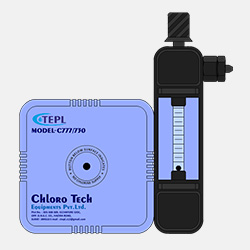
Chloro Tech Type 730 Chlorinator is a high quality, low cost solution feed, vacuum unit.
Proven design, rugged construction and use of best available materials assure precise gas feeding, low maintenance, dependable operation and long life.
The type 730 Chlorinator is also available with single or multiple metering tubes for feeding chlorine to one or more points of application. Single and dual tubes may be mounted directly on the front of the chlorinator regulator or remote from it. Remote metering tubes are mounted on the plastic coated bracket which can be located adjacent to or remote from the regulator. Each metering tube is supplied with its own ejector and rate valve and operates independently of the others. The metering tube is connected by a single gas line to the chlorinator.
The Type 730 is available for manual or start-stop operation. Similar units are available for feeding Ammonia Carbon Dioxide or Sulfur Dioxide gases.
Design Features
COMPLETE SAFETY
Vacuum operation assures safety for plant operating personnel and equipment. Built in safety features prevent damage to chlorinator under abnormal operating conditions.
ECONOMY
Low initial cost, multiple metering tubes, simplicity of installation and maintenance, rugged corrosion resistant construction and contribute to the most economical chlorination system available.
FLEXIBILITY
Wall or ton container mounting and optional multiple metering tubes and ejector provide complete Flexibility for applications requiring chlorination at two or more points.
MINIMUM MAINTENANCE
Superior design of ejector, with double check valve and drain relief prevents any back flow of water into the regulator. The heated combination trap-manifold assures that no liquid chlorine will be carried into the regulator.
Operation
The chlorine gas from the cylinders or container enters the manifold, where it is filtered and electrically heated to evaporate any liquid chlorine which may be present. Water flowing through the ejector creates a vacuum which opens the inlet valve to admit the gas into the regulator. The spring-opposed diaphragm regulates the vacuum at this point to a closely connected valve.
The gas passes through the flowmeter/s and the rate control valve and then to the ejector/s where it is thoroughly mixed and dissolved in the water and carried to the application point as a solution. When multiple metering tubes and ejectors are used, each operates independently of the others. Adjustment of one of the gas flow rates has no effect on the rates.
The system is completely under vacuum from the ejector to the gas inlet valve during operation. If the water supply to the ejector is stopped, or the operating vacuum is lost for any other reason, the spring loaded gas inlet valve immediately closed to isolate the chlorinator from the gas supply. Any gas under pressure which might enter the regulator is vented from the system through the built-in pressure relief valve. If the source of chlorine is exhausted or the gas-line plugged, an excess vacuum valve in the regulator closes to prevent any moisture being pulled back into single indicator pops out of the regulator to indicate that the gas supply has been interrupted.
The ejector is provide with a diaphragm-operated back check valve in addition to a ball check valve to double insure that water does not leak back into the regulator when the system is shut down. The ejector is also furnished with a drain to relieve any water which might leak past the check valves.
Engineering Specifications
CAPACITIES
Standard metering tubes are available with the following maximum capacities of chlorine gas: 0.5, 1.5, 5, 12.5, 25, 35, 50, 100, 125, 150, 200 and 250 kg. PD (Kilkograms per day).
FLOWMETER RANGEABILTY
20 to 1 for any one flowmeter, e.g. a chlorinator with a maximum capacity of 50 KgPD can measure and control gas feed over the range from 25 to 50 KgPD. Each metering tube scale length is 4” for easy readility.
EJECTOR REQUIREMENTS
Reasonably clean water at any pressure between 3 and 300 psig is required to operate the chlorinator. Water consumption and required inlet pressures are dependent upon chlorinator capacity and ejector discharge pressures. Ejector is required for each metering tube and rate valve.
POWER REQUIREMENTS
240 v. to operate 6 KW electrical heater in gas inlet. The heater is furnished with a 10’ cord and a plug with redial ground pin.
CONNECTIONS
Chlorine gas inlet: 3/4” NPTI
Ejector Water inlet: 1” NPTI
Solution Outlet: ¾” or 1-1/2” NPTE or 1”, 1-1/2” or 2” hose. Hose size determined by water flow required to operate chlorinator. Alternate 1” NPTE thread may be used for in line ejector mounting. Which is usually reserved for 50 Kg. PD max.
Capacity
Safety vent : 3/8”tubing.
MOUNTING
The chlorinator is mounted directly on the gas inlet manifold which is provided with four slotted holes for wall mounting or with a yoke for ton container mounting. The ejector is provided with a wall mounting bracket.
ACCURACY
+ 4% of set feed rate.
CONTROL MODES
Manual adjustment of the rate valve alters feed rate. On multiple meter units, each meter is equipped with a rate valve. Start-stop control is obtained by installation of an automatic valve , (controlled by timer, flow, pressure, or pump control device) will start/stop the chlorinator.
OUT OF GAS INDICATOR
Manually reset visual indicator signals when the chlorine gas supply is exhausted or interrupted.
MATERIAL OF CONSTRUCTION
Kralastic, PVC, tantalum, Hastelloy-c Teflon, Kel-F Silver and extra heavy duty boro-silicate glass. Mounting manifold is ductile iron with corrosion resistant covering.
SHIPPING WEIGHT
Approximately 15 Kgs.