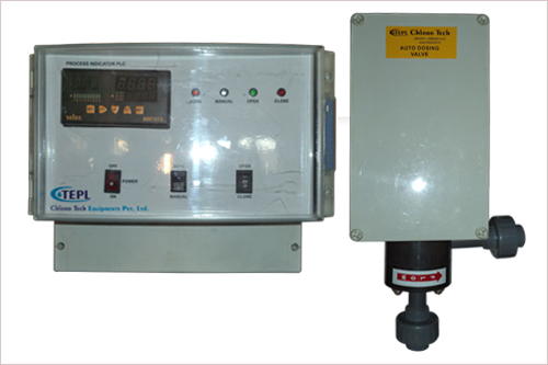
Technical Data Sheet of Auto Dosing Valve
| Data Sheet of Valve | |
|---|---|
| Body | PVC / ABS |
| Stem | Sonically ‘V’ notched, Hastalloy‘C’/PVC/ |
| Monal | Bottom Connection mounting on Header Line |
| Seat | Teflon / Kayner / EPDM |
| Rack | Hastalloy ‘C’ / Monal |
| Pinion | Hastalloy ‘C’ / Monal |
| Gear | Monal / Hastalloy ‘C’ / Nylon / PVC |
| ‘O’ Ring | Viton |
| Type | Manual with Automatic arrangement. |
| Data Sheet of Actuator | |
|---|---|
| Out put Motion | Linear / Rotary |
| Out put speed | 0.26 mm/sec |
| Stroke Length | 40 mm max. |
| Manual Override | Provided Hand wheel with clutch. |
| Travel Limit Switches | Provide – 2 Nos. (1NO + 1 NC) |
| Torque Limit Switches | Not required as motor used in still duty. |
| Local Position Indicator | Provided continuous type. |
| Class of protection | IP 55 |
| Duty Regulating /ON-OFF | Regulating |
| Area of Operation | Safe |
| Data Sheet of Motor | |
|---|---|
| Type | Non blocking A.C. Synchronous motor |
| Supply | 220 VAC 50/60 Hz 1 Phase |
| Insulation Class | B |
| Actuator / Panel mounted Positioner | PP 300 provided |
| Input for positioner from controller | 4 – 20 mA |
Introduction
General
These instructions apply to the wall and panel mounted Automatic gas control vale. Component instruction manuals and supplemental data are referenced where applicable. Maximum capacity of the valve is related to:
The gas being dispensed.
The capacity of the vacuum regulator.
The capacity of the ejector.
| Specifications | ||
|---|---|---|
| Maximum capacity (Chlorine) | Ranges | |
| PPD | Kg/h | |
| 100 PPD (2 kg/h) | 100 | 2 |
| 50 | 1 | |
| 25 | 0.5 | |
| 10 | 0.2 | |
| 200 PPD (4 kg/h) | 200 | 4 |
| 100 | 2 | |
| 500 PPD (10 kg/h) | 500 | 10 |
| 200 | 4 | |
All capacities are listed for chlorine gas. To determine capacities for sulfur dioxide, multiply each value by 0.95. For carbon dioxide, multiply each value by 0.78. For ammonia, multiply each value by 0.5.
Signal input:
a. 4-20 mAdc
Power Requirements: 120 Vac or 240 Vac, 50/60 Hz, single phase
Power consumption: 15 VA
Display: LED bar graph,0-100% of full valve capacity, in 10% increments. Bottom LED indicates power ON.
Alarm Contact: Unpowered TRIAC rated 0.5 amps @ 240 Vac maximum. Selectable N.O or N.C at valve closed.
Ambient Temperature: 32’ F to 125’ F (0’c to 50’c)
Dosage Ratio: Maximum – 2:1, Minimum – 1:5
Meter panel
Vacuum Gauge – 0-030 inches of mercury
Meter Size – 6”
| Vacuum Line connector Size | |||
|---|---|---|---|
| Feed Rate | Length of Vacuum Line | ||
| 100 feet (30 m) | 200 feet (60 m) | 500 feet (150 m) | |
| To 50 PPD(1kg/h) | 3/8” | 3/8” | ½” |
| 100 PPD(2g/h) | 3/8” | ½” | 5/8” |
| 200 PPD(4kg/h) | ½” | 5/8” | 4/3” |
| 500 PPD(10kg/h) | 5/8” | ¾” | 1” |
Principle of Operation
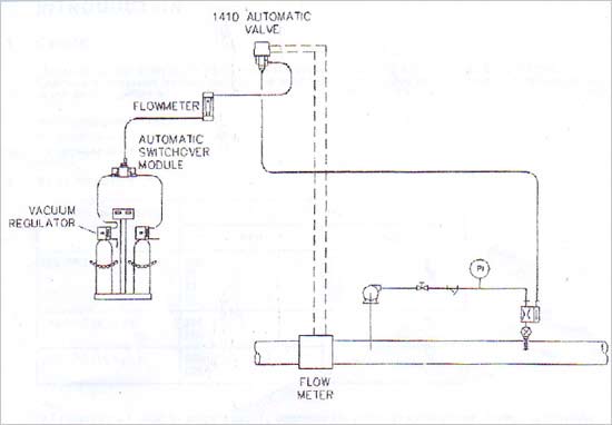
Install the automatic gas control valve or panel between the vacuum regulator ( or switchover module, if provided) and the ejector or chemical induction unit.(Figure 1 ) When the valve receives an input signal, typically from a process flow transmitter, if compress its present gas feed to the desired gas feed and repositions the valve until a balance is achieved. The result is a linear gas feed rate adjustment in proportion to the input signal to provide versatile automatic control.
A dosage control knob is provided to manually adjust the gas dosage. Once set, the dosage maintains a fixed ratio between the gas feed rate and the process flow, regardless of flow variation. The dosage control knob permits adjustment to the dosage ratio to the 1/5 of the design dosage for any process flow up to the maximum flow rate. It also permits an increase in the gas feed dosage up to the twice the design dosage at half the maximum flow rate. A manual or auto switch and manual rate adjustment switch are provided to manually operate operate the valve in the event of loss of input signal or manual override.
A solid state electronic switch contact or TRIAC is provided to activate a remote device when a fully closed valve condition occurs. The TRIAC when energized, act as a switch closure or opening and connects into the hot side of the power line of the remote device.
The valve may be fitted with an optional dual potentiometer (0-500 ohms) where the resistance value is proportional to valve position. When the potentiometer is connected to the Resistance to current signal conversation module, an inferred gas flow rate output signal is available. A local line power ON/OFF signal is not provided since constant power is maintained to the electronics boards.
Accuracy of the gas feed rate is dependent upon maintaining a constant deferential pressure between the valve inlet and outlet. This may be accomplished by increasing the vacuum level measured at the valve’s outlet 14.6” of mercury minimum when sonic conditions occurs or installing an external differential pressure regulator in the downstream vacuum line.
Automatic gas control valves 50 ppd / 1 kg/h and over, use the sonic principle without the differential pressure regulator. for capacities of 25 ppd / 0.5 kg/h or less, the differential pressure regulator is supplied to provide improved accuracy and adjustability by increasing the resolution.
NOTE: Valves 50 ppd (1 kg/h ) and over require a minimum vacuum of 14.6” inches of mercury at the valve outlet to operate at sonic flow. To assure this vacuum level, selection of the next higher capacity ejector is recommended.
Wall panels contain a vacuum gauge and a 5” meter panel to aid in monitoring the feeder operation.